
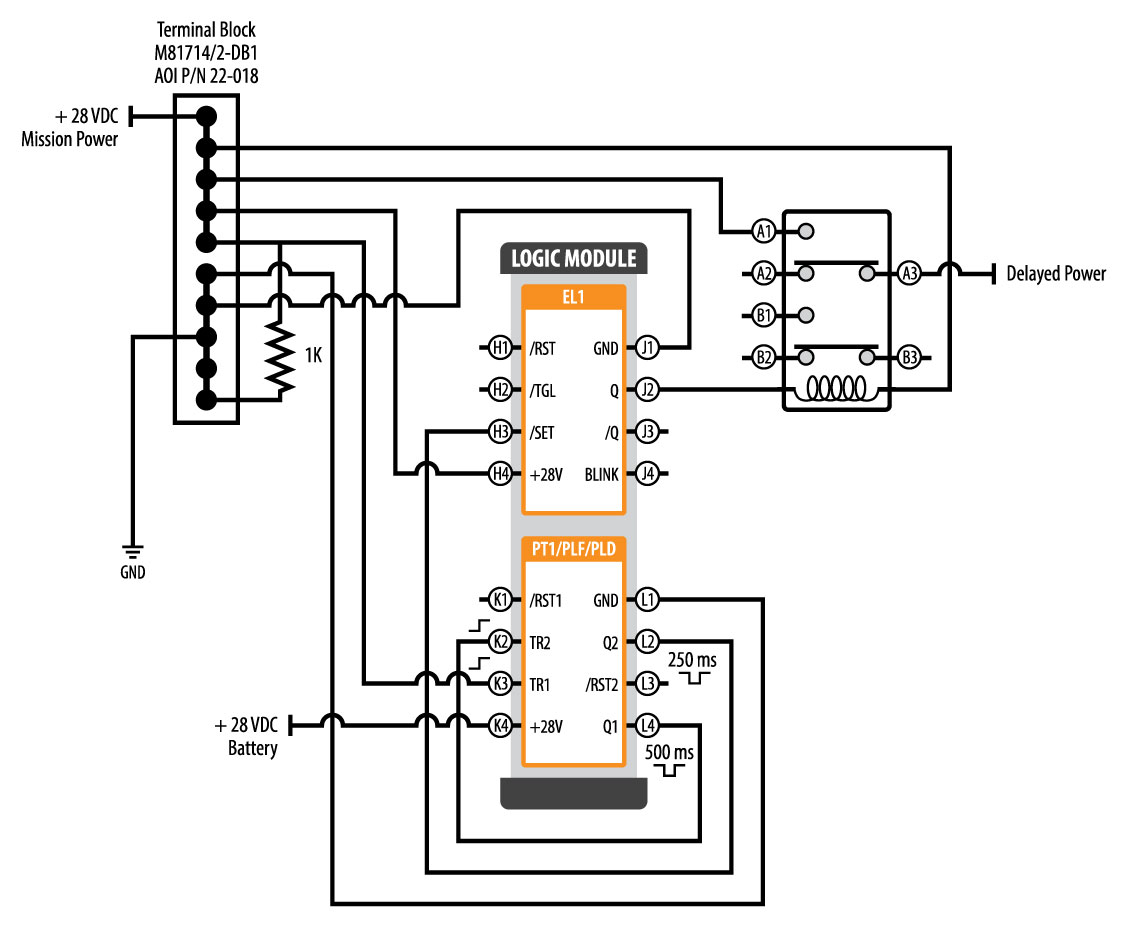
Timer Delay Relay Wiring Diagram
However, when the input signal is lost, the relay requires a certain amount of time to return to its previous condition. The bueler time delay relays are unlike the vast majority of other relays you.

Dayton Time Delay Relay Wiring Diagram Gallery
Time relay refers to a kind of relay whose output circuit needs to make an obvious change (or contact action) after adding (or removing) the input action signal in a specified and accurate time.

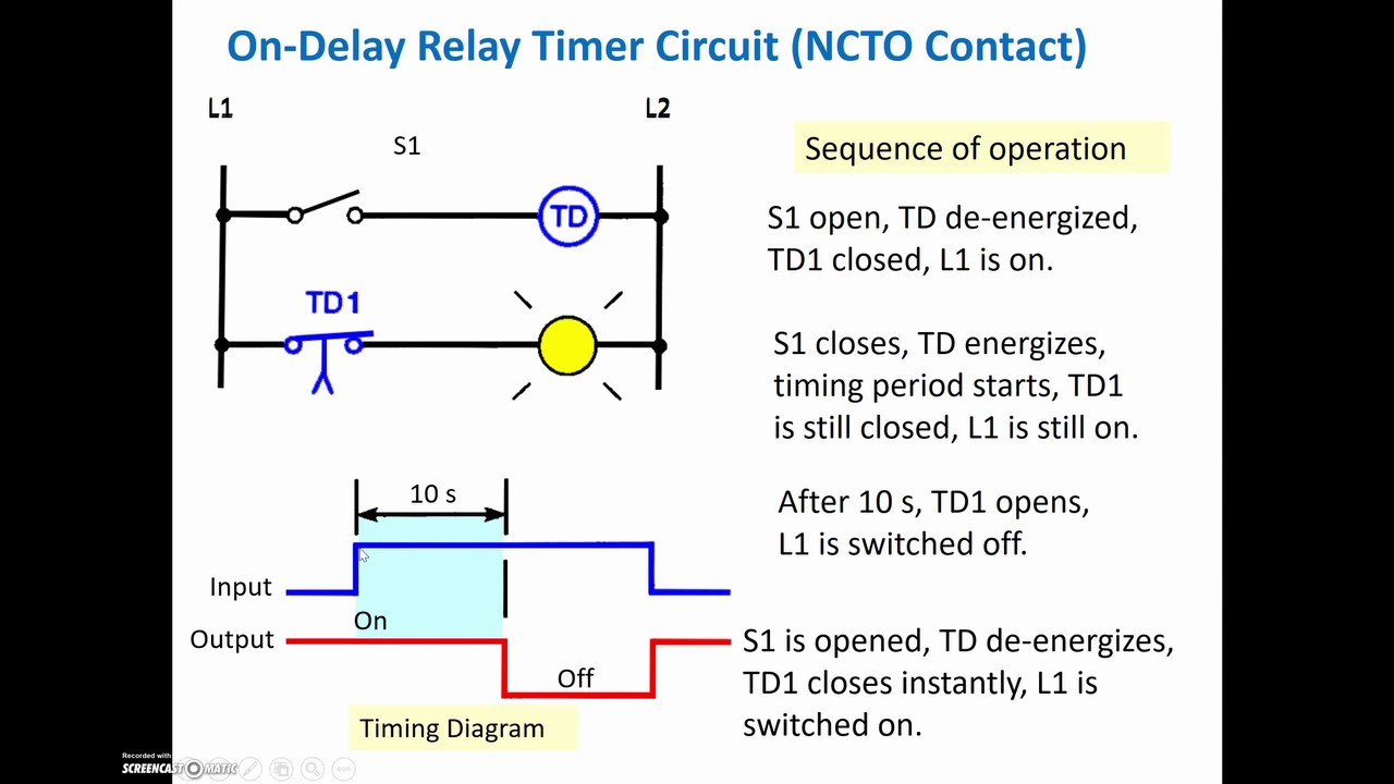
Timer delay relay wiring diagram. The timer function #1 is on delay, it allows to supply power after a period of time (t). October 19 2019 1 margaret byrd. The input sighal is invalid if it gets a trigger signal again during delay time op.
Not merely will it help you attain your desired results quicker, but also make the complete procedure less difficult for everybody. Hager timer switch wiring diagram. During the circuit design with the timer relay and variety of timer configuration, questions such as
Each component should be placed and linked to other parts in particular manner. The contacts remain in the on state until the timer is Time relay wiring diagram and wiring.
Wiring diagram for timer relay wiring diagram line wiring diagram. Understanding timer delay relay function. When the input signal is gained, the execution component immediately receives an output signal;
Every time delay relay has an internal relay (usually mechanical) with contacts that open & close to control the load. Hager eh011 timer wiring diagram. This post is about the staircase timer wiring diagram in the diagram i use the on delay timer finder 8 pin relay re electrical circuit diagram timer diagram.
(except for gt3f "true power off delay"). Relay will turn on for time op after getting a trigger signal and then turn relay off. There are a few questions in there, so i will try to address them all.
Off delay timer relay wiring diagram. Get results from multiple engines. This is just one of the solutions for you to be successful.
Wiring diagram for timer relay wiring diagram line wiring diagram. 1 on delay voltage, the time relay (t) upon application of input begins. Solid state timer relay time delay relays to cycle a traffic signal using 555 ic motor control systems part c electromechanical off dol starter circuit for working principle timers advanced simple on diagram 12v delayed turn or howto 326 327 series wiring st3pf tdr 120vac 24vdc with ac ons switch 12 volt drok 0 1s timing circuits explained manufacturers dc 24v.
Find instant quality info now. On delay timer circuit diagram wiring diagram contactor with push button circuit diagram of delay timer on off power off delay timer circuit diagram 2 way lighting circuit triggering transformer push button fan switch light activated switch circuit diagram wd081 text. With such an illustrative guide, you'll be capable of troubleshoot, stop, and complete your tasks easily.
It is an electrical component used in a circuit with a lower voltage or a smaller current to switch on or off a circuit with a higher voltage and larger current. Each component should be set and linked to other parts in specific way. Relay will turn on for time op after getting a trigger signal and then turn relay off.module will reset and stop timing if it gets a trigger signal again during delay time op.
Relay will turn off for time cl after getting a trigger sighal and then relay will turn on for time op.relay will turn off after finish timing. Solid state timer relay electrical academia using time delay relays to cycle a traffic signal 326 327 series on struthers dunn grt8 s1 asymmetric cycler best supplier in china for 10 years geya 555 ic dc 5v. Otherwise, the arrangement will not function as it should be.
Schneider electric low voltage distribution cct15232 mins timer 05 20min. Relay will turn on for time op after getting a trigger signal and then turn relay off.the module will restart timing if it gets a trigger signal again during delay time op. They are represented by the dotted lines in the wiring diagrams.
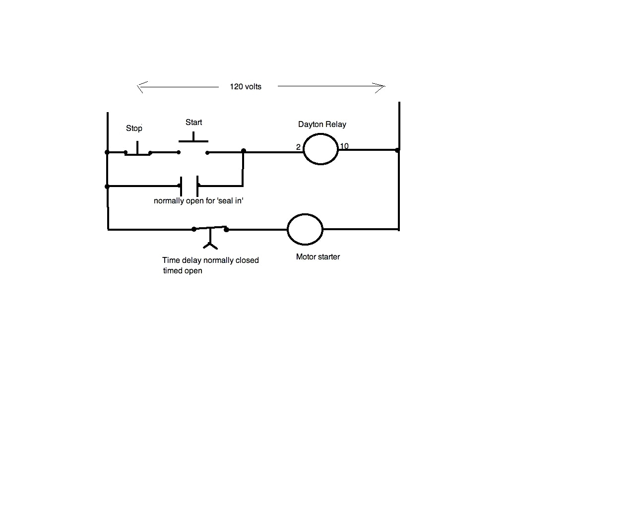
Note that the user must provide the voltage to power the load being switched by the output contacts of the time delay relay. Time relay 230v ac ezn001 hager relays eibabo com. When the set time has elapsed, the relay contacts transfer to the on state.
Another image hagar eh connected to 3 phase v must have line fuse or fuse carrier installed to protect timer and wires to timer. Understanding all the time delay relay functions available in multifunctional timer can be an intimidating task. At the end of the time delay (t), the output is energized.
Dayton Time Delay Relay Wiring Diagram A652

Dayton Off Delay Timer Wiring Diagram Collection
Delay On Break Timer Wiring Diagram
Dayton Time Delay Relay Wiring Diagram Gallery
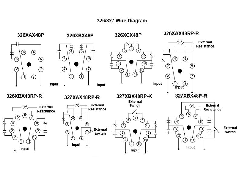
Item 327XBX48P300120VAC, 326/327 Series Time Delay Relays On StruthersDunn

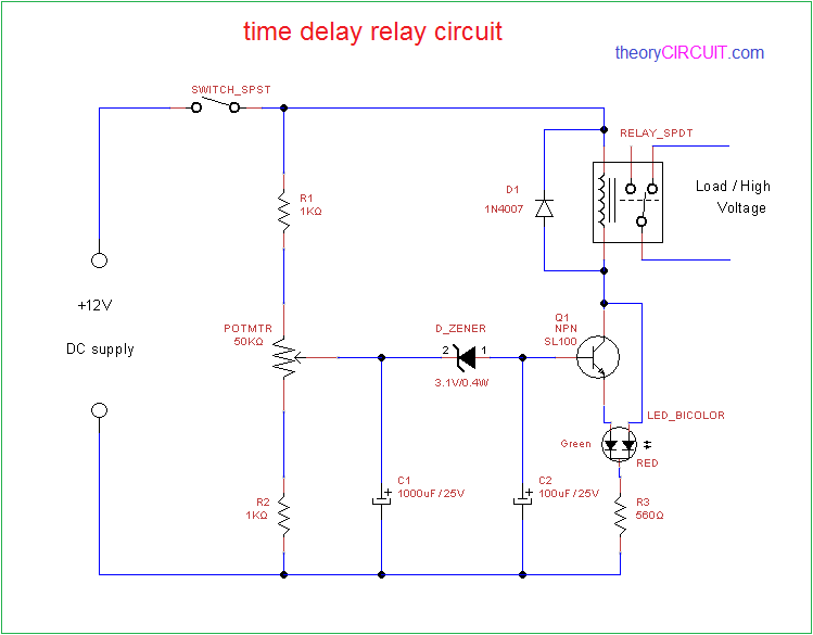
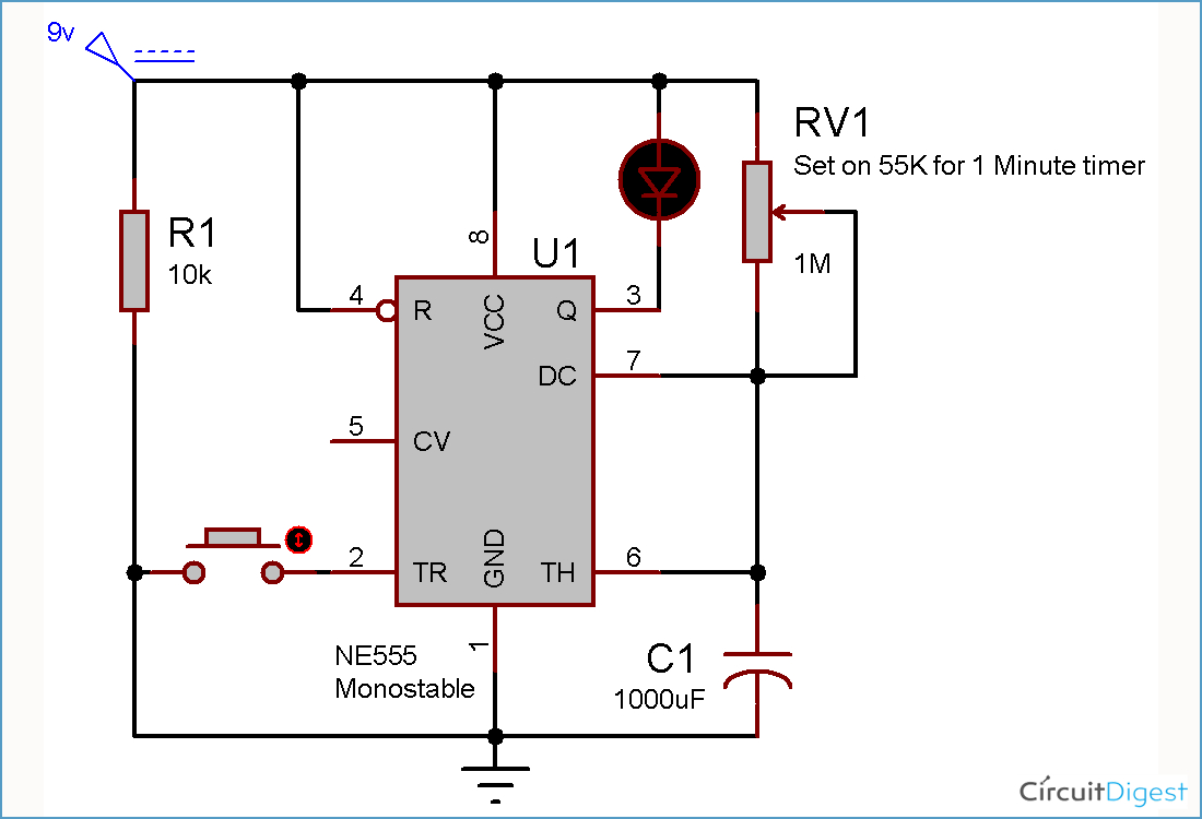
Simple Delay Timer Circuits Explained
Time Delay Relay

Dayton Off Delay Timer Wiring Diagram Collection

Dayton Time Delay Relay Wiring Diagram Gallery

Dayton Time Delay Relay Wiring Diagram Gallery

Timer Relay Circuit 4 Wiring Library • Insweb.co
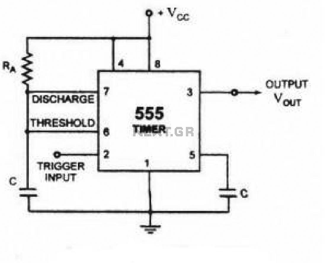
Solid State Timer Solid State Relay Timer Electrical Academia

Relay OFF Time delay timer by using NPN Transistor and Capacitor
Time Delay Relay Replacement
Time Delay Relay Wiring Diagram Download Wiring Diagram Sample
Dayton Time Delay Relay Wiring Diagram A652
60 Best Of Time Delay Relay Wiring Diagram


Dayton Time Delay Relay Wiring Diagram A652
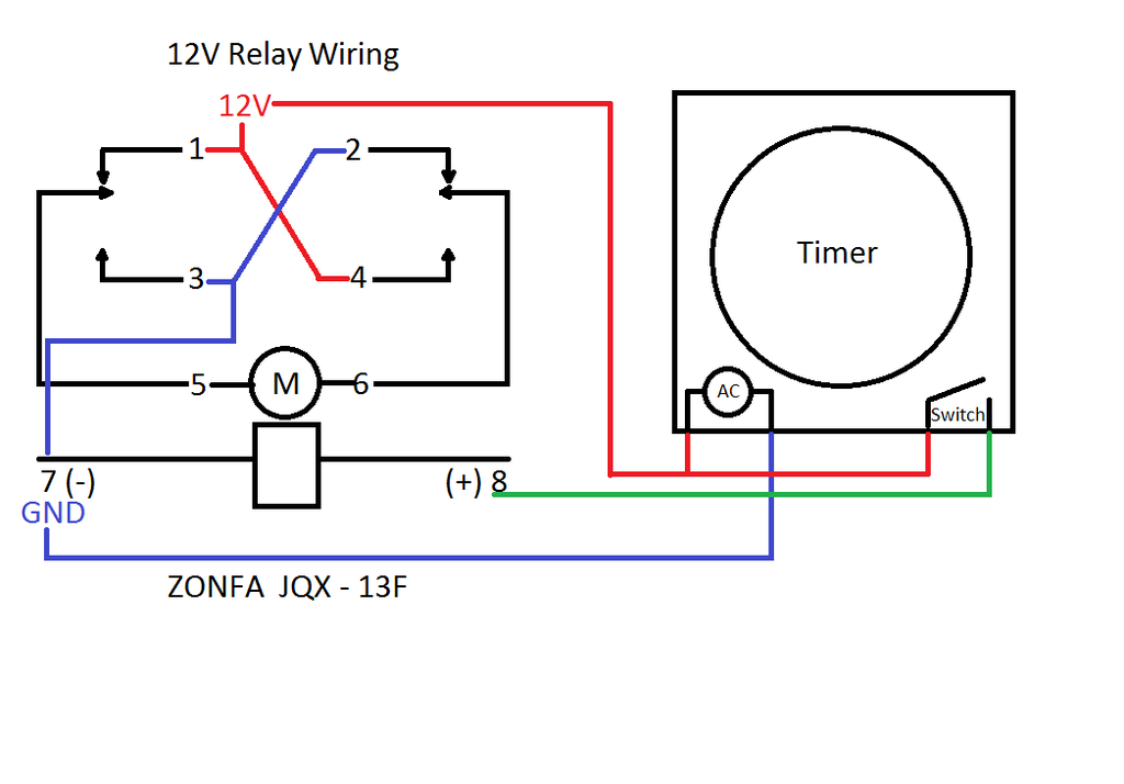
12V Time Delay Relay Wiring Diagram Collection
